Saturday, March 31, 2012

Middle Earth (the Albatross Around My Neck), Pt.2

Last time here I was waiting for the Sculptamold to dry. Well, after 24 hours it was still moist in some spots, and didn't take sandpaper very well. No problem, I'll just start the second terrain board. I placed it beside the first, and marked where terrain features crossed the board's edges. Then I commenced to slicin' and dicin'. I continued the creek about half-way across the board when I decided to have the creek exit from under the wall through a culvert. No problem, it just meant the pond, which turned into a spring, would have to go back to being a pond again. I considered scratch-building the culvert, but I had an N-scale viaduct that was the perfect  size. I'd just trim it down a little, and carve the foam a little, and I'd be done..........Right?

Has this ever happened to you? You start with a minor project, almost a throw-a-way, that you think will take an hour at most, and it GROWS and GROWS and GROWS completely out of proportion? Like this font size? Well, has it?

It's happened to me. I had a perfect little culvert ready to install in the foam. Just need to carve a little here. Y'know, since I'm carving, why not carve a little more, and I can add some wing walls. Wow, I think this needs a sluice. And a holding pool. Every new feature was an improvement, but its location on the board will make it hard to see. I kept trying to stop, "This is enough," or "You're wasting your time." But I couldn't, I just couldn't.   But I'm getting closer. So let me bring you up to date on the culvert.

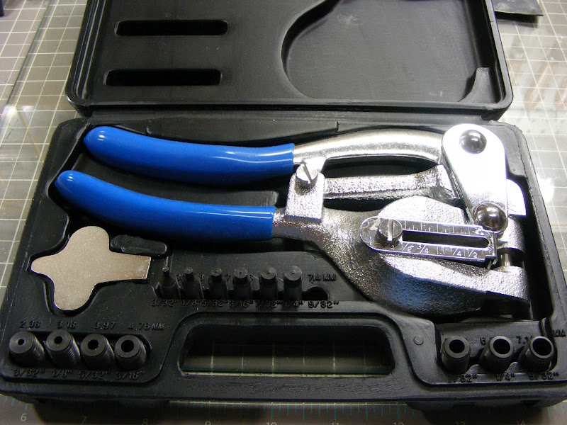
First, this is the knife I am doing all the foam cutting with.


Here you can see the procedure I forgot to take a picture of in the last installment. This is going to be a shallow ford, so I used 1/2" foam core instead of 1/4". Where the channel narrows and turns left, is where the culvert will be.


Here it is after two days. The original model was simply the face with the semi-circle, and the top cap. I had carved out for it in the foam, and planned to carve the adjoining foam to look like rock faces. Instead, I made the long and short wing walls (just the upper part).I used the remaining stone cap and some styrene strip to cap them both. Using more styrene, I made the step ledges, then added the lower walls underneath. After that came the stonework inside the arch, the angled runway, and the bottom stonework. At some point during all this, the corner stones with the beveled tops appeared, as well as the plain styrene sheet on the very bottom.


At this point the plan was to have the foam rocks right against the outside of the wing walls. However, if I held the rock walls back, I could detail the outsides of the wings. Here also the plan was to have the bottom curved styrene sit flat on the foam, and carve the creek channel away from it. I would cover the styrene with sand and small stones.


To protect the top of the culvert, I fitted a piece of Plastruct's Polished Stone to it.


Gotta have bars. These are 3/64" brass rod.


 I had the Polished Stone out anyway, why not use a little more? I covered the bottom styrene sheet, put some spacer strips underneath, and attached a piece that would be the creek bed.


Another view of the top. The rear edge of the stone would sit next to the wall.


Okay, every time I made an addition, I had to carve out more foam so it would fit. At this point, the culvert was a hair thicker than the 2" of pink foam, so I cut all the way through, put a piece of 1" Styrofoam underneath, then carved another 1/2" into it. Now my terrain boards are 3" thick, which really doesn't bother me too much. It adds a lot of stiffness (flatness), plus gives me more lee-way in my carving. Speaking of carving, my attempts to carve and fit rock faces into the spaces here in place were becoming very frustrating. Alright, I would remove the culvert, carve and add the rocks to it at the bench, cut out a bigger hole for it in the boards, then fill in with Sculptamold around the whole she-bang. Which is what I started to do................when I remembered those Woodland Scenics rubber rock-molds I had stashed.


New Plan! The molds were designed with plaster in mind, but I had a little resin left from the buttress project that I knew would be going bad soon, so I mixed it up and poured it in. This left me with plenty of rocks to play around with. I came up with the arrangement you see in the next couple of pictures.


Next I used Woodland Scenics Flex Paste and Foam Putty to fill in the gaps between the rocks.  I finished the first coat late last night, and left them to dry. Left them to dry? Geez, where have I heard that before?


I feel like I'm getting the upper hand on this bastard, and hope to be getting it done soon. I know, I know, "Famous last words." Next time, there will be water. Don

Sunday, March 25, 2012

Middle Earth (but It's Pink!), Pt.1

I figured it was time I put the Fort in context. In other words, get off my butt and make some terrain. Even from the first I had a pretty good idea of what I wanted, so I grabbed some pink insulation board, positioned the Fort, and began drawing the cut lines for the terrain features. Next I grabbed my WS Hot Wire Cutter and began slicing.......grabbed my hot wire cutter and began............ hot wire cutter and began.........shoot, the thing was dead. It worked the last time I used it, but that was probably three years ago. At least it fit in the trash bin.

So, I looked through my blade drawer and found a two inch blade that cut the foam like butter. I don't remember buying this blade, so it probably came out of Eve's stash. As long as it worked.

OK, some parameter's. These boards are 2' x 3,' standard LotR fare. I figure 4-6 of them will allow room for the Long Walls, as well as giving the Evil side room to maneuver. These boards were actually cut down from some 2' x 5' blanks I was preparing for a FoW Omaha Beach table. The foam was glued to wooden frames (to keep them flat) with tongue-and-groove edges (to keep them aligned). Man, that is too much like work. I was not so nearly ambitious here. I'm hoping that if I'm careful applying the various ground covers, the foam will remain flat. If it twists or curls, I have some 1/4" Masonite that will do the job.

The first requirement is that  the Fort's sides were not parallel to the board's edges. Boring! It is hard to see in these pictures, but the building is angled with the right-front corner an inch or two closer to the camera. It doesn't take much to get rid of that 'static' look. The second requirement was the Fort should be raised one layer of foam higher than the normal ground-level. Thirdly, I wanted a small shelf of ground with a sharp drop-off in front of  the baffle wall. Last of all, there had to be a long, grassy causeway from the Fort to ground-level. I achieved all those goals, plus a few more.

In these two shots, you can see I used one of the big cut-off scraps to raise the Fort one layer. You can easily see the drop-off in front of the baffle wall, as well as the causeway. The 'gutters' on either side were cut to an exaggerated depth. I knew I would cover the board with plaster cloth or Sculptamold (or both), and they would fill that extra depth.


Here are a couple of those extra goals. I started with a creek that ran into a small pond. I cut completely through this layer of foam. I will add a new bottom in a minute.  Then I took  a two-arch, N-scale viaduct, cut off one of the arches, then widened it from 1" to 3". Finally I trimmed the foam to accommodate the bridge.


If you were wondering what the stone pedestal at the foot of the causeway was for, here you are. There is a pedestal on the other side also. I have enough silicon left to make a mold of this guy, or I could just use the 'fallen statue' that came with this one.


A view of the creek.


I can't believe I didn't take a picture of the next step, but I think I can explain it with this shot. I couldn't just leave the creek and pond bottomless. I needed something nice and flat to apply a water-effect to. I pinned a 1/4" piece of foam core under it, and cut straight down through the bevel and through the foam core. Where the creek sides were vertical, I cut the foam core flush with them. I ended up with a piece that fit (almost) perfectly.


The following pictures show the application of the first layer of Sculptamold. I love this stuff, a combination of plaster and paper mache.


I changed the direction of my thinking. The water course will now begin here, emanating from a spring on this islet.


This first application of Sculptamold was fairly thick, and I've left it to dry overnight. Hopefully it won't shrink too much. I'll sand it today and apply a second, 'soupier' layer to cover any boo-boos.


The last thing I did last night was glue down the big piece the Fort sits on. Oh, did I mention this earlier? I guess I haven't used this glue for a few years either. It had dried so much in the bottle, I had to cut the entire top off. It was now the consistency of children's paste, but it  went on perfectly with a putty knife. A dozen magazine holders 'clamped' the piece down. Looks like I need to make a trip to the hobby shop on Monday.  Thanks for looking.  Don

Friday, March 23, 2012

Cheiroballistra, Pt.3

There I was, sitting at the bench with three bolt throwers at various points of completion. It's not that I don't want to finish them, it's that with every one I start, I find a better, more efficient way to make one. And don't forget, I wanted them smaller. So the first, bigger thrower I made will be the only one that size. I guess now was as good a time as any to finish it off.


The first thing I wanted to do was cap off the ends of the upright (torsion) tubes.  On the historical unit these caps were dome-shaped with a center nub. This hole punch with interchangeable punches and dies has no problem going through brass sheet. And while playing around one day, I discovered if you  use the correct size die for the hole you want, but use a punch one size smaller, it makes a perfectly domed circle, even having the nub.


Here they are glued in place. Next I wrapped thin wire around  the windlass and attached it to the ratchet/trigger mechanism. That little devil took the most time of the project. I tried several designs with different materials before settling on this one. It was the simplest, and I think I can duplicate it for the others. The bow string is brass, a little larger than scale, cause I never wanna see no droopy string. I pre-bent the wire, fed it through the trigger, and cut it to length. Confession Time! One of the reasons I went through so many trigger designs was they were too long. The bow string went straight across, with no bend in it. It didn't look like the string was drawn. Even after shrinking the trigger as small as possible, it was barely bent. The arms were bent back at a sharp angle, so I broke the glue bonds, and moved the arms forward. But they were so long, that even at the shallower angle, the string still didn't look right. Finally I clipped 1/4" off the ends that go in the tubes, to get this passable pose. How many people would have even noticed this? Well, I would have.


The bolt is brass rod hammered to a wicked sharp point. The fleches are styrene. (One got knocked off.) The wire at the front is there to steady the thrower while I took these pictures. Not sure if it's staying.


The latest, smallest yet, v.3. The torsion tubes are shorter (only 5/8"), closer together, with more delicate cross-pieces. The bolt trough and the arms are also shorter.  Here you can see it next to the down-sized v.2.


I figure I'll pre-cut the pieces for 3-4 more of each.  Construction goes pretty fast as a production line process.  Don

Tuesday, March 20, 2012

A Two-Fisted Choppin' Fool

The other day I was chatting with some fellow modellers on the Terragenesis Forum, and they were asking me how I liked my Chopper II. I like it overall, and use it quite a bit, but I said I wished it had two chopping arms. They  were curious as to why, and I said that even though I've made several jigs for it to cut multiple shapes, sometimes I need to make simple straight cuts while using the jig. It would be nice to make them without having to remove the jig. Now I've planned on making a two-armed chopper for a long time, having bought two replacement arms in the last year, and those conversations have spurred me to finally build it. Here is what I came up with.

The arms are actually replacements for the Chopper I. The base is a piece of MDF I cemented some Formica to. (A scrap from a previous workbench.)  I drew a line across the base, about 1-1/2" from the top, and clamped a heavy, metal straight-edge along that line. Next I cut a brass I-beam to length, then snugged it up to the straight-edge. After that I drilled holes through the I-beam, into the base, and secured it with tiny screws, making sure the beam did not deflect away from the straight-edge as I tightened them.
Now to the left arm. (This one would make 90° cuts only.) These arms are designed to be bolted through from underneath. I placed the arm where I wanted it, marked the location of the bottom screw hole, then drilled down from the top. Once through, I made a countersink from underneath, then bolted the arm down snugly, but not tightly. This allowed me to hold one side of a small square (you can see it under the X-acto blade) against the I-beam, then pivot the arm until the blade was tight against the other side. I had achieved  90°ness. Now I could mark the location of the top hole, drill, countersink, and bolt it down. Finally, I took a 6" section of ruler, and screwed it against the I-beam.


Now to the right arm. I wanted this one to make common angle cuts. I considered having the arm pivot from side to side, but that wasn't practical. So I attached this arm the same as the other. You will notice I have the arm against the I-beam. This is so the blade of this arm does not interfere with the cutting lane of the other arm. Next I cut four 3" lengths of brass angle, and drilled two holes in each. Now I used triangles to position those pieces. I had a 45-45-90° triangle, and a 30-6-90° one as well. I had to make the 22-1/2° angle with some styrene and an angle finder. I located, drilled and nailed the two bottom pieces, then did the top two. I spaced them so each position would handle a strip up to 1/4" wide.


And here are my test cuts.


A closer look at the ruler.


Finally, I took some styrene scraps and two magnets, and made a depth-stop which snaps onto the ruler.


The arms are available from Walthers. Maybe you'll be inspired to make one of your own.

Don

Monday, March 19, 2012

Cheiroballistra, Pt.2

Pt.2? More like v.2. Not to worry, I'll be finishing v.1, but as I said in the previous post, it turned out bigger than I wanted. My second attempt would be smaller.

Do you know what's hard? Well of course, comedy is hard, but that's not where I'm going. What's hard is trying to align and drill holes in a round brass tube. On the first thrower, I took care to mark and drill as accurately as possible, yet there were some small discrepancies. Now, do you know what's easy? Well of course, dying is easy, but that's not where I'm going. What's easy is aligning and drilling holes in a square brass tube. And that's what I did.


To find the center of the tube, I set my dividers by eye to what looked like half the width. Then drawing one leg along each side, I scribed two lines down the middle. I was lucky, and both lines were close enough to each other, I was able to mark the holes' locations without further adjustment. BTW, these holes locate the cross braces.


Next  I needed holes to position the bow arms. I turned the tube over,  marked their locations with a scribe, then scored a line across each corner with a knife-edged file. This allowed me to locate and continue filing with a round-edged file. I made certain to hold the file at a 45° angle to both adjacent sides, and proceeded until I just broke through. Then from each location, I drilled through diagonally to the opposite corner. (Pay no attention to the two holes in the middle of the side. The real holes are opposite of this side.)


Next I slide a round tube into the................Wait. Whhhaaat? You thought I was going to use square tubes for......... nooooo.  No, the square tube is a jig for drilling holes in the round tube. OK, the round tube slides in until it hits the wire which blocks the jig. Next drill a hole in the top location.


To keep the tube aligned, this wire with a leg at 90° goes into the hole just drilled.


Now a hole is drilled in the bottom location.


Being careful to not let the alignment wire pop out, turn the jig over, choose one of the holes, and drill in towards the center. (Remember which location you drilled from. When you make the second upright, you'll drill from the opposite location.)  This jig positions the bow arms at a 135° angle to the cross pieces.


Finally use a razor saw to cut the tube flush with the jig. This produces a 3/4" upright.


In these two shots you can see how I changed and simplified the new thrower from the original. First, the upright tubes are a smaller diameter, and seem to have something inside them. (I'll get to that in a minute.) They are also closer together, and the cross-supports are round rod instead of flat-stock. I do have some flat-stock wrapped around the uprights. This is where the bolt trough will attach.  The bow arms are shorter. Now, back to what's inside the uprights. I had some plastic tube that fit perfectly, so I cut them flush and re-drilled the holes. I found the arms and cross-supports were held snugly and in perfect alignment. After the problems I had gluing the original thrower, I had at first planned on soldering this one. The plastic tube makes that step unnecessary.


I wrapped some more flat brass around the uprights, as well as completely around the bolt trough.


I made a pivot/swivel and placed it directly under the uprights, for better balance.  To give me an idea of how high this thrower would sit, I placed it in the stand of the original, then set it on this proof of concept mock-up of the shooting position. Too tall. I could make a smaller  base for it.


Here it is, shorter (the center post is only 3/8" tall) and a slightly different design.


Maybe I can make it a little lower.


My three ballistae side by side. The bolt trough on v.2 isn't much shorter than the original, but is  certainly more delicate looking


I may play around with the location of the pivot/swivel to lower the thrower a little more, but overall, I think I have the model I want to go with on the walls.  Comments and questions always welcome. Don